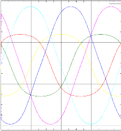
Dynamic analyze for the induced voltages in the three phases of the coils over the rotor angle.
Initial Situation
Siemens Servo Motor 1FT6
This universal synchronous motor is used for many high-performance motion control applications. It uses permanent-magnets, has very small torque ripple and an almost constant torque characteristic.

The motor we analyzed uses 36 nuts, 8 permanentmagnets, 4 poles.
In this analysis our goal is to analyze for the induced voltages in the coils over the rotor angle. This can be done quite easy in 2D using the magnetodynamic timedomain solution type.
Appropriate Method
2D Magnetodynamic Timedomain Analysis
To analyze for induced voltages we have to set the rotor to the realistic rotation velocity of 3000 U/min and calculate for the voltage in the coils.
 Picture: Calculated Voltage
The picture shows the calculated voltages of the three phases (smaller curves) and the linked voltages of the phases (larger curves).
Result
Torque and Voltage Constant
The voltages on each coil are computed in the dynamic analysis by MAGNETICS for NX.
The dynamic analysis also allows to calculate for the voltage constant Ke that describes the behaviour of an electric motor.
In this case we simulate Ke to 145, while measurements of the 1FT6 give 144 what is in reasonable agreement.


