In this example we show a FEM analysis of a transformer that is coupled with a 1D Villard circuit containing diodes and capacitors. The resulting voltage is influenced by loss effects (nonlinear saturation and leakage inductance).
Initial Situation
Electronic Components
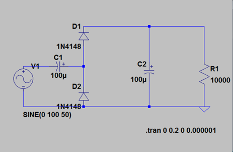
Goal of this use case example was to analyze a transformer in FEM in context of his real circuit. By doing the analysis this way we are able to capture the behavior of nonlinear saturation and leakage inductances of the transformer geometry and their effects on the circuit. The used circuit is a Villard model that contains diodes, capacitances and resistors. The Villard circuit performs a doubling of the voltage and is used in many electronic devices.
Next picture shows the used circuit. Goal is to compute the time dependent voltage at resistor R1.
 Picture: The used Villard Circuit
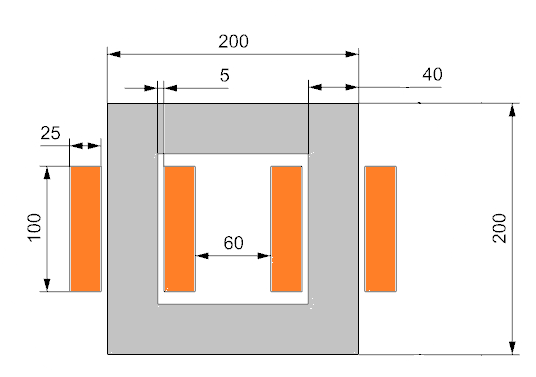
Instead of the supply voltage V1 in our example we will couple a finite element model of a 2D transformer to the circuit. Additionally to the Villard circuit we apply a 2 Ohm resistor to the transformer that leads the electrosheets into saturation. The transformer model is shown next.
 Picture: The used Transformer to be coupled to the circuit
Some of the input parameters are:
N1 = 1000
N2 = 100
U0eff = 230 V
RL=10000 Ohm
C1=C2= 100 mu Farad
D1=D2= 1N4148
This problem is also described and analyzed in the following:
“Integration analoger Schaltungselemente im Magnetfeldsolver des NX Systems“, Master Thesis Christian Korolonek, University of Applied Sciences RheinMain, 2013.
Appropriate Method
2D Magnetodynamic Time with Circuits
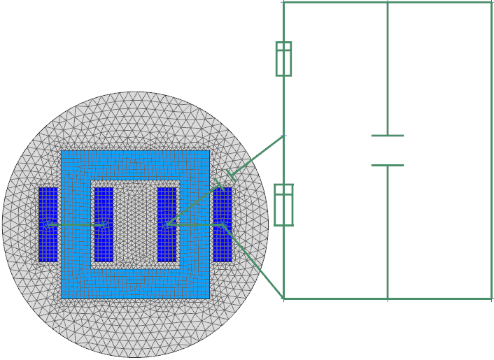
This kind of problem is solved in NX Magnetics using a Magnetodynamic solution type and the application of 1D circuit elements. Possible elements are connectors, resistors, capacitors, inductors and diodes. The nonlinear behavior of diodes is realized by the use of voltage dependent resistors. The FEM model is set up using 2D and 1D-elements as shown in the next picture. Diodes and capacitors are marked by a symbol. Resistors are simply shown as lines.
 Picture: Mixed 1D / 2D elements for the Transformer and Villard Circuit
Result
Losses affect Voltage
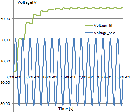
The blue curve having 30 V represents the transformers output voltage. Because of the winding relation there is a factor of 1/10 to the given input voltage of 220 V (rms). The second curve represents the desired behavior of the voltage at R1. The curve shows a step by step increase until it reaches nearly the double of the blue curve. In an ideal situation there had to be exactly a doubling, but in this analysis effects of saturation and leakage inductances are included that make the results more realistic than analytic formulas.
 Picture: Behavior of Voltage at R1 resulting from the Electromagnetic Analysis


