This part of a power electronics assembly shall be modified to reduce the inductivity. So we perform an dynamic analysis to find the inductivity value.
Initial Situation
Power Electronics Part
The component to analyze is a simplified geometry of a power electronics assembly as it is used for frequency converters. Electric current flows from the bottom left to the top right electrode. In case of a switch off an overvoltage may appear because of inductivity effects. Therefore the goal of this analysis is to compute the inductivity value for the geometry.
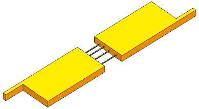 Picture: Simplified Part of a frequency converter
Then, by changing the geometry it should be possible to reduce this value and optimize the overvoltage behaviour of the part.
Appropriate Method
3D Magnetodynamic Frequency Solution
The geometry is modeled in NX CAD and then transfered to the Advanced Simulation module. Also the air volume has to be created. Using the Magnetics solver a solution type "3D Magnetodynamic Frequency" is performed. The material (copper) is assigned from the library and the mesh is a standard tetrahedral type. In the output requests the inductivity result is activeted.
The picture shows the CAD Model of the copper part and the air volume.
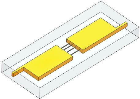 Picture: CAD Model
The following picture shows a detail view of the mesh in the area of the connecting cables.
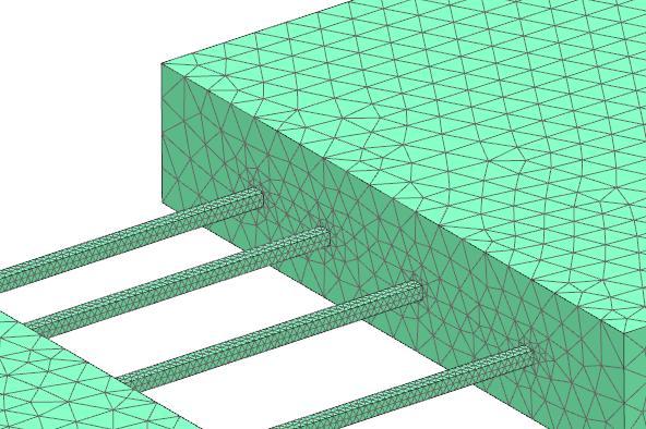 Picture: Detail Mesh View
Result
Inductivity Value and Current Distribution
The calculated Inductivity value was 5,5e-9 Henry. By changing the geometry it was possible to reduce the inductivity value and the danger of overvoltage for the part.
The next picture shows the computed current distribution in the part as a color plot. It shows the current density and by this the cables can be checked for their current contribution.
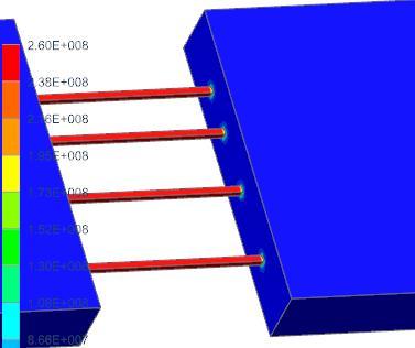 Picture: Computed Current Distribution
And the following picture shows arrows pointing in the current flow direction. This result can be used for plausibility checks.
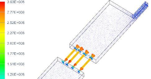 Picture: Current Flow Direction


