This example demonstrates an asynchron motor. It is belonging to the group of test examples that are well documented. See in this description how induced voltages are computed and compared to the reference data.
Initial Situation
Three Phases Induction Motor TEAM30
This example is an asynchron motor. It is belonging to the group of test examples that are well documented. In this description it is shown how induced voltages in the three phase are computed and compared to reference data.
 Picture: CAD model of induction motor TEAM30
The input data for the analysis are the following:
- Phaseangle: 60 degrees,
- Frequency: 60 Hz,
- Current: 2045,175 Ampereturns,
- Rotor Velocity: 1200 rad/sec = 11459 U/min
Appropriate Method
2D Magnetodynamic Time
The solution of this problem is carried out by the the magnetodynamic a-v formulation in the time domain. To account for the movement of the rotor there are two methods to chose between: Moving Band or General Motion. In this case we decide for the moving band method because of the simple geometry.
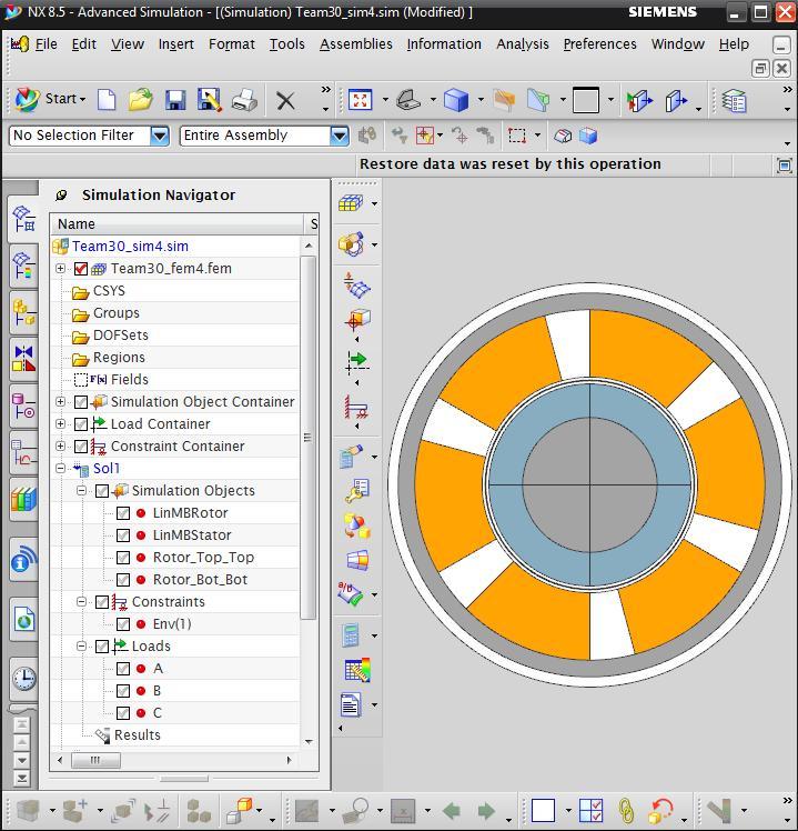
In the fem file meshes and material properties are applied, while there exist only linear materials in this study.
 Picture: Simcenter with Team30 Motor
In the sim file all boundary conditions and solution settings are defined:
- The rotating field resulting from the coils,
- the velocity information for the rotor,
- Initial conditions;
- Time step data.
Result
Voltage and Potential
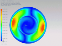
Prior to the voltage results we first show the computed potential result for this asynchron motor. Click on the picture to start a movie.
 Picture: Potential Result (click to animate)
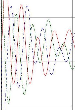
Additionally to the potential there are also flux density, losses, forces, torque and voltage results calculated. In the next two pictures we show graphs of all three voltage phases A,B,C over time. After a transient oscillation that is shown in the next picture,
 Picture: Period of transient Oscillations for Voltages in Phase A, B and C
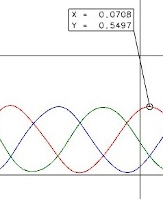
the voltages become balanced as shown in the following picture. The maximum value is found as 0,5497 Volt. The reference result from the TEAM30 documentation is given as 0,5562 Volt. The deviation becomes 1% what is an acceptable value.

Picture: Voltage in Phase A, B and C of Induction Motor
These results show how a asynchrone machine can be analyzed in Magnetics for NX. They also demonstrate good agreement between NX and reference values.


