In this case study a linear motor is designed and using a step by step enforced motion analysis the forces acting on the coils are determined.
Read full article
Download as PDF
Initial Situation
Synchron Magnet Linear Motor Force Analysis
A linear shaft motor shall be designed and analyzed using NX CAD and the Magnetics Solver. Therefore a first design approach shall be done in form of a parametric CAD model that allows easily variation of geometry. In the simulation our goal is to find the curve showing forcees over position. Magnitude and ripple of this curve shall be studied using different geometric and electric variations.
 Picture: CAD geometry of Linear Motor Design
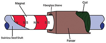
The principle of linear shaft motors bases on the generation of lorentz forces that result from permanent magnets and currents from coils. Further explanations can be found in www.machinedesign.com.
 Picture: Principle of Linear Shaft Motor
Appropriate Method
2D Axisymmetric Model with linear Joint
A CAD model of this new design approach is build. Each magnet and coil is represented by a CAD face. Because of axisymmetric conditions we only sketch the half of a section. Colors characterize magnets and coils with u, v, w phase currents. Using synchronous modeling techniques we define an CAD expression that controls the linear position of the forcer geometry.
 Picture: The parametric CAD Model
We create an 2D axisymmetric FEM model in NX using automatic meshes and assign physical properties. For this first test we use N30EH magnets and coils having 25 turns.
 Picture: Part of the mesh using quads and tri elements
In NX simulation file we define u, v and w harmonic phase currents. We use a magnitude of 15 A. The phase shifts are defined that way that one cycle corresponds with the length of two magnets.
 Picture: Definition of Phase Currents on six Coils
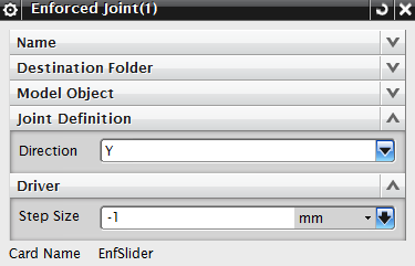
Next a linear motion joint is defined. We chose the technique General-Motion that allows defining the motion in form of a CAD parameter that is varied step by step. The enforced joint allows no dynamics. Alternatively we could use the dynamic joint that would allow the analysis of the motor's acceleration.
 Picture: Definition of the enforced linear Motion Joint
Result
Forces over Position
In the analysis the plunger went over a distance of 80 mm in 80 steps. The resulting flux density in the magnets and current in the 6 coils can be controlled in the postprocessor by color plots or by running a movie.
 Picture: Flux density and Coil Currents at first step
![]() Picture: Flux density and Coil Current shown by Arrows
Picture: Flux density and Coil Current shown by Arrows
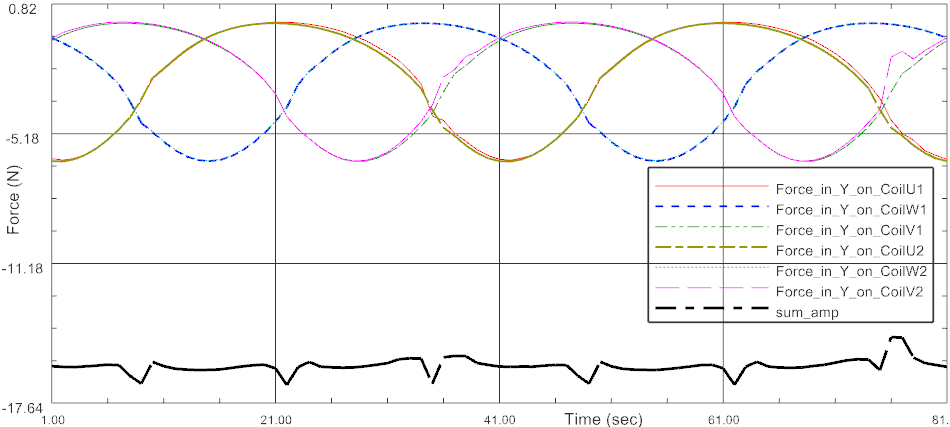
For each coil we can determine the force. In the next picture all single coil forces and the overall sum is displayed.
 Picture: Single Coil Forces and overall sum
The result shows that the mean overall force for this linear motor under the given conditions will be 16 N. Minimum and maximum values would be 14.6 and 16.8 N. Now that we have an appropriate analysis model the next step in the design process will be the variation of geometric and electric Input data with the goal to fine tune the results to given requirements.


