The application to simulate is a linear motor to be used in a future magnetic levitation railway. We publish this with kindly permission by HARDT GLOBAL MOBILITY.
Initial Situation
Study and Optimize 3D Behavior
The application to simulate is a linear motor to be used in a future magnetic levitation railway. We publish this with kindly permission by HARDT GLOBAL MOBILITY. Next picture illustrates the application.
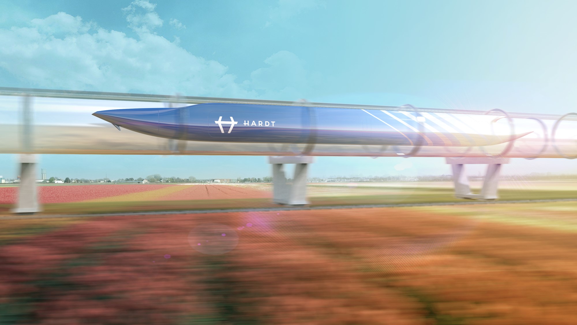 Picture: Illustration of the application (With kindly permission by HARDT GLOBAL MOBILITY)
There is a laminated steel beam and a U-shaped magnet suspended below it at a few centimeters. The U-shaped magnet consists of a permanent magnet or a superconductor, a laminated iron core, and also two electromagnets at the ends of the U. The steel beam has slots for an aluminum/copper wire. When a current flows through this wire, a force is generated in the direction of the beam, causing the U-shaped magnet to move. The poles of the U-shaped magnets also have slots for an aluminum/copper wire, which generates a current on the U-magnet side as a generator for the suspension. See the following figure of Transrapid as reference, to which the system is similar (although in this figure the U is continuous and does not have permanent magnets/superconductors):
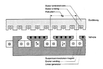 Picture: Motor system of a Transrapid as reference, to which the system is similar
Points of interest at this simulation are as follows:
- The magnetic field
- In the gap between the magnet and the beam
- In the magnetic material, taking into account saturation and permeability
- The stray field further away from the magnet
- The forces on the U-magnet
- Vertical forces to see when it levitates
- Longitudinal forces due to the current running through the copper wire
- Lateral forces when the magnet is displaced with respect to the beam
- Eddy currents generated due to the movement of the magnet
- In the copper wire
- In the laminated steel
- The currents generated in the wires of the U-shaped magnet
Appropriate Method
Stepping Motion in 3D Dynamic Solution
A CAD and FEM model of the motor is created. This could be done in either 2 or 3D. We choose 3D to capture the stray field. All material properties, linear and nonlinear are taken from the library and applied to the corresponding meshes.
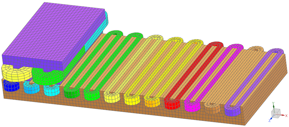 Picture: The FEM model of the linear motor. Air meshes are blanked for better visibility
The simulation of motion is realized through a so called General Motion feature. This feature moves the rotor elements by a user given displacement step for each time step. The airgap between rotor and stator is remeshed automatically by this feature and the next simulation step can be solved.
The requested results are switched on in the solution dialogue. This is shown in the following picture:
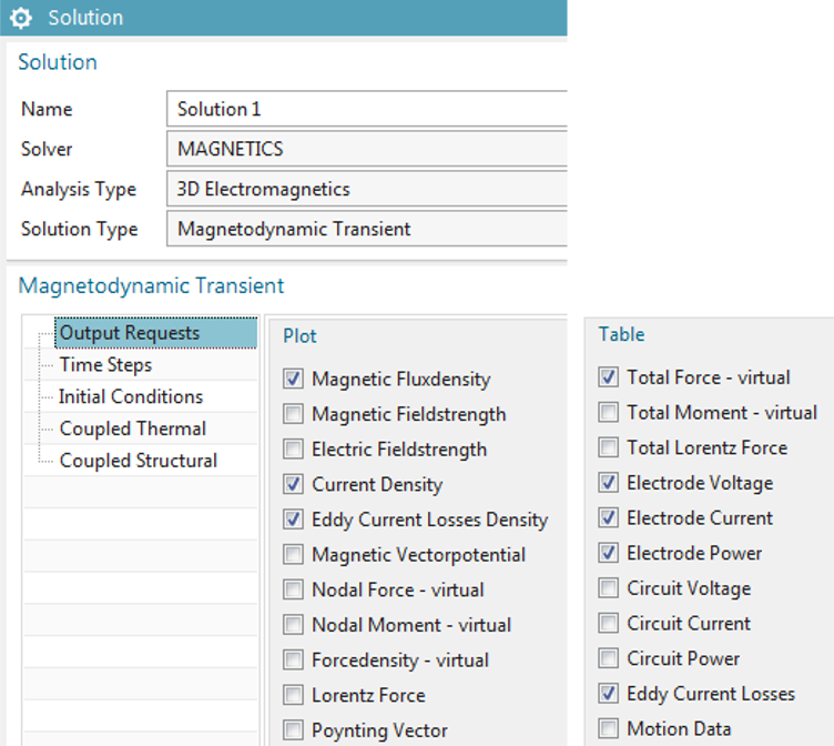 Picture: The dialogue showing possible outputs for this 3D Magnetodynamic Transient solution
In this case we use a General Motion feature of enforced type. Alternatively we could use a dynamic General Motion feature that would compute the size of the displacement steps automatically through magnetic forces and mass properties of the rotor.
Solve is done on a simple computer with 4 cores and 32 GB memory. Because of nonlinear Newton-Rhapson iterations one step is done in about 1 min. We run 136 steps and therefore need about two hours to compute the following results.
Result
Stray Field, Force, Induced Currents/Voltage
As requested before we are interested in finding those results. We start with a movie (click to animate) showing the magnetic flux density as it behaves while the rotor moves.
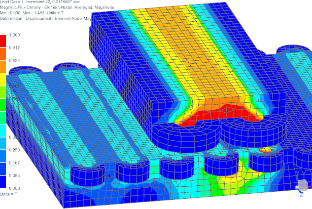 Picture/Movie: Magnetic Flux Density (click to animate)
Then we investigate the computed rotor forces and their variation over the position as shown in the next picture.
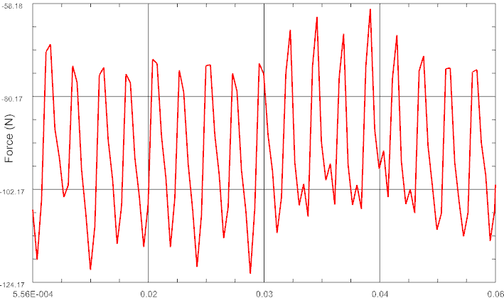 Picture: Forces over rotor position
Next we show the Stray Field that can be investigated best by looking at vectors of the magnetic flux density in a sniped view cutting through the rotor. Notice that this changes over the position.
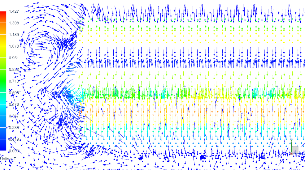 Picture: Stray Field
Induced Currents are computed automatically in magnetodynamic solutions. From those the system can compute eddy current losses who often are of interest because of their effect on the thermal management. We show those Eddy Currents together with the applied currents in the next picture (Click to animate).
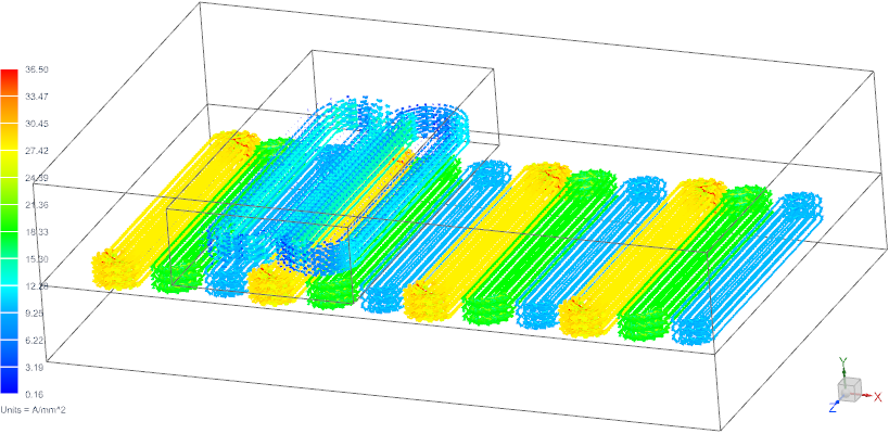 Picture/Movie: Applied and Eddy Currents (Click to animate)
The last result of interest is the behavior of stator voltages in the rotor coils. This result is required for knowing the electric power consumption and for the selection of power electronics being compatible to this motor. Also this allows predicting the motor efficiency. In the next picture we show such voltages in one phase (4 coils use this). The behavior also allows checking the rotor position.
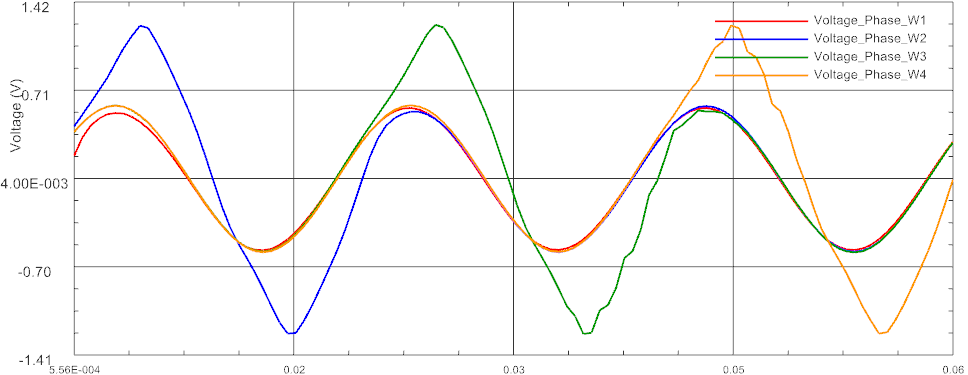 Picture: Induced Voltages in stator coils of phase W
Using these results it is possible to fine tune the linear motor behavior and adapt it to given requirements. Geometric changes are done easily in the NX CAD system, mesh updates perform automatically or with some user interaction. Electric parameter sweeps can help finding optimal settings.


