FEM Analysis of the induced eddy currents in the plates and the stationary temperature and other results.
Download as PDF Download NX Files
Initial Situation
AC Induction Heating
This example deals with a high voltage transformer and induction heating. One or two steel-plates are positioned over the coils of the transformer. Goal is to find the induced eddy currents in the plates and the stationary temperature on them while the 300 turn-coils are driven by 10 A, 50 Hz in opposing directions.
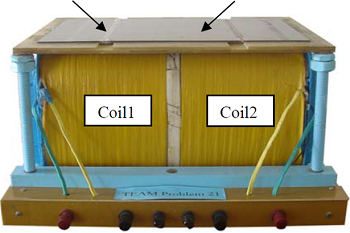 Picture: HV Transformer
The dimensions and material data are taken from team benchmark problem 21. Some of the input data is:
Coils:
Copper, Electric Conductivity 58e6 S/m
Steel:
Magnetic, nonlinear BH-Curve, Electric Conductivity 6484000 S/m, Thermal Conductivity 1.4 W/m-K, Specific Heat 434 J/Kg-K
Appropriate Method
3D Magnetodynamic Frequency Solution
To compute for eddy currents in the case of AC excitation the magnetodynamic solution in the frequency domain is convenient. The nonlinear B-H-curve is used in this analysis but preciseness of the nonlinearity is not as good as in the time domain.
The solution starts with a CAD model of the transformer in NX. Around it there is an air volume modeled.
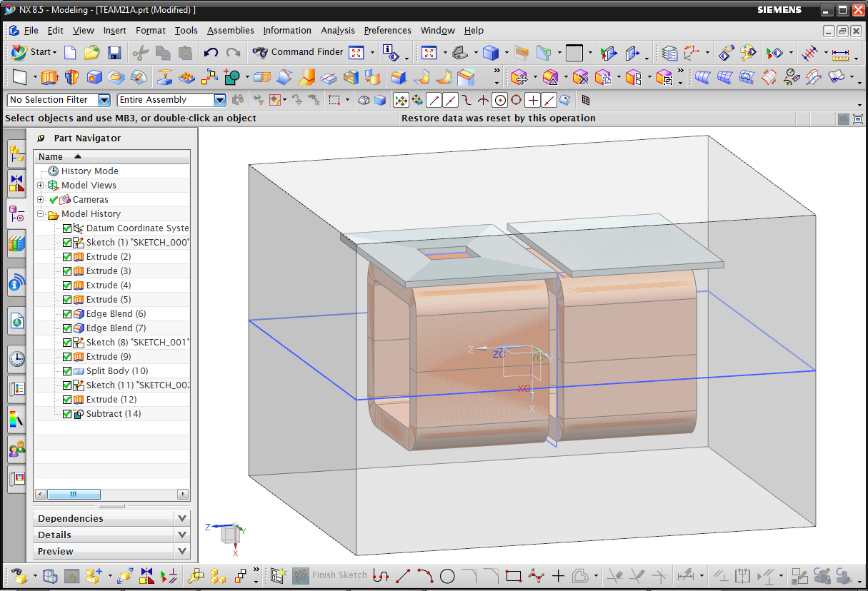 Picture: Transformer CAD model in NX
The meshing is done next. We use hexahedral elements for both the coils and the plates. These elements lead to best results in finite element solutions. These elements can easily be connected to the outside air that will be meshed by tets using pyramids in the transition area.
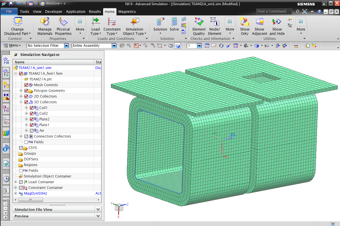 Picture: Hexahedral Mesh
One important aspect is the definition of the windings for the 3D coils. NX Magnetics is able to derive the winding directions from a curve. So we use one of the tangent edges of the coil. The next picture shows a small arrow in every element that is derived from the inside CAD edge. By this way all coil currents will use these directions what corresponds nicely to a stranded coil.
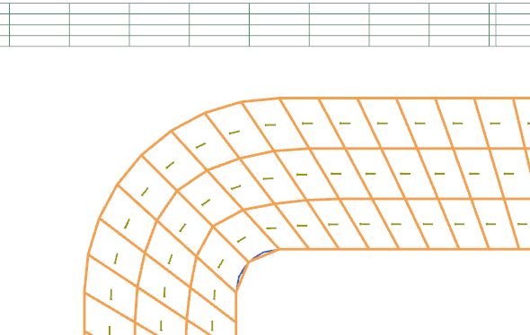 Picture: Small arrows in the coil elements point into the current direction
After the two excitation currents in opposing directions and the thermal convection condition are defined the job is solved.
Result
Temperature, Flux Density, Eddy Currents
First goal of this analysis was to find the temperature-distribution on the two plates as it can be seen in the next picture. Because the Initial temperature was set to 20 °c we computed an increase of about 10 °C in the near of the opening.
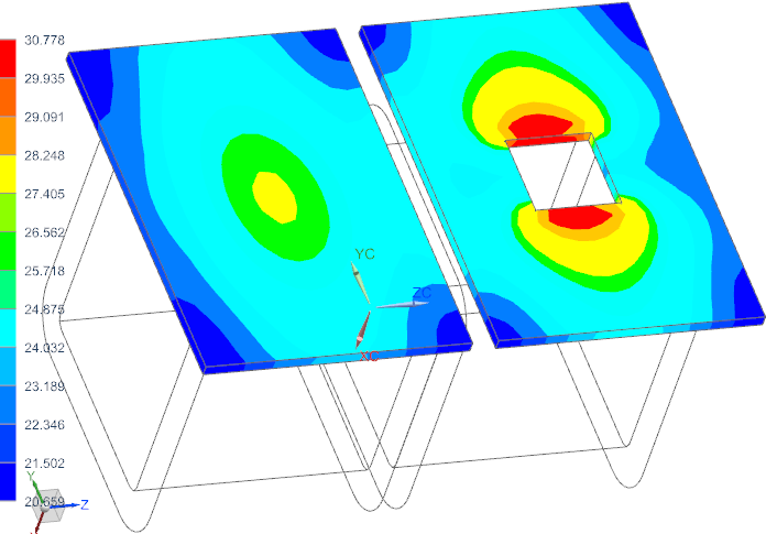 Picture: Temperature on Plates
The next plot shows the flux density in the plates resulting from induction effects.
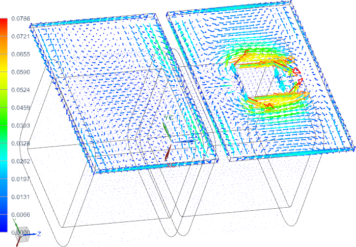 Picture: Flux density by Arrows
Next picture shows the computed eddy currents in the two plates.
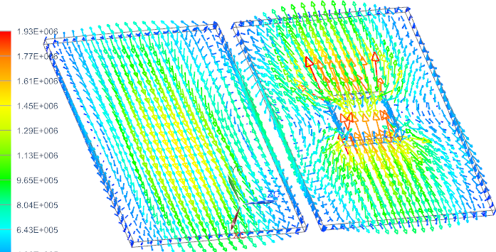 Picture: Eddy Currents
It has been shown that using these methods in Magnetics for NX it is possible and simple to analyze HV transformers, find eddy currents and temperatures. In the shown type of analysis we used a simple convection condition on all outside faces with a constant convection coefficient. In an extended analysis we could transfer the computed eddy losses results from the electromagnetic solution to the NX Thermal/Flow solver. This would allow handling non-constant convection coefficients and sometimes lead to more realistic results.


