This example shows a FEM analysis of a Circuit Breaker that is placed in a carbon fiber box. Induced eddy currents and the shielding effect are investigated.
Download as PDF Download NX Files
Initial Situation
EMC Shielding with Fiber Materials
In industries like energy management of buildings, also in automotive (e-cars) or aircrafts the assemblies and surrounding geometry are influenced by electromagnetic fields produced by electronic components like circuit breakers or electric motors.
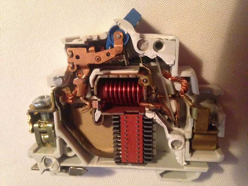 Picture: Typical Circuit Breaker Assembly
For choosing the best geometry, cooling, materials and operation conditions it is necessary to know how large the field strengths become outside shielding boxes and at various distances. Although there do exist effective ways for EMC shielding for example using mu metals today many parts must be manufactured of carbon fiber or other complex materials. Prototypes are expensive and too time consuming so simulations must be performed.
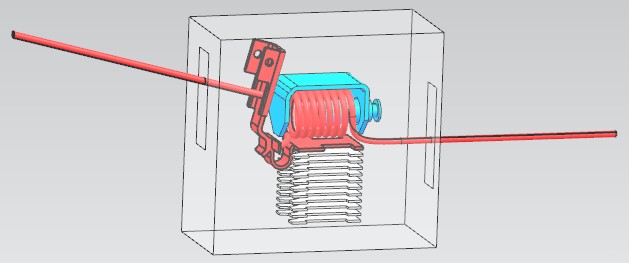 Picture: CAD Model of investigated Circuit Breaker
In this study a circuit breaker under short circuit condition is analyzed for the electromagnetic field and how this field is shielded by a box that is made of carbon with orthotropic fiber directions. Goal is to find the magnitude of the magnetic flux density at various position in and outside the box.
Appropriate Method
Transient Dynamic with conducting orthotropic Sheets
The analysis starts from an NX CAD model that contains the coil, the plunger and several small sheet metals from the circuit breaker. There is a shied box around the circuit breaker which has openings for input and output wires. This box is a sheet body while the rest is solid geometry. Also the air volume is in the CAD model.
Several finite element meshes are created in NX. All of them are given material properties as it is usual in electromagnetic analysis with NX Magnetics.
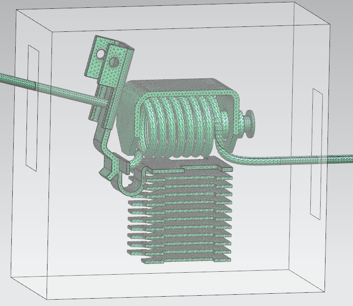 Picture: 3D FEM meshes that are used to model the Circuit Breaker Geometry
The shield box is meshed with 2D elements using the Physical property Conductive Sheet which allows to model thin conducting sheets. Coordinate systems define the directions of the orthotropic material.
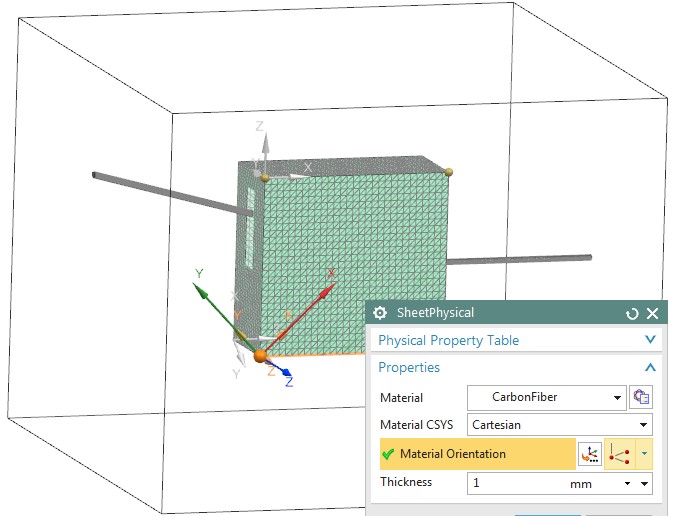 Picture: FEM Model of the Box. Due to thin Geometry we have set up the box with 2D Sheet Elements. Material is orthotropic
To model the carbon fiber we apply an orthotropic material with 3 different electric conductivity values. In direction of fiber 200000 S/m is applied while the others directions have a small value. Using local coordinate systems the orthotropic material is oriented on the 6 faces of the shield box. The picture shows this definition in NX’ material editor.
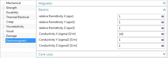 Picture: The Material Properties that we give to the Box Elements
In the Sim file we define transient current on the wire’s end caps. We apply the following analytic formula which forces short circuit conditions:
2^0.5*100*(Sin[2*Pi*50*$Time-1.57]+Exp[-$Time/0.0455]*Sin[1.57])
We run 30 time steps with an increment of 0.1/150 s. The model has about 500000 degrees of freedom, needs 16GB memory and the solve job takes about 30 min of an Intel i7 with 4 cores machine.
Result
Eddy Currents and B Field
The computed field solution contains results for each time step. We have requested eddy currents and the magnetic flux density. The following pictures illustrate the solution.
First we want to see the eddy currents on the shielding box. The next pictures show them in contour and vector plot.
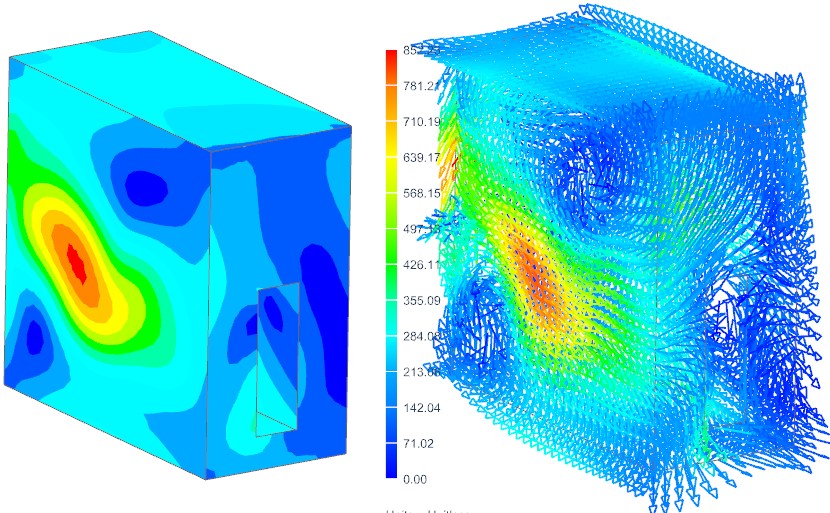 Picture: Eddy Currents on the carbon Shielding Box
To get an understanding of where the induced currents in the box come from we want to see the circuit breaker together with the box in one picture. This is shown in the next picture.
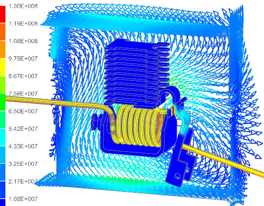 Picture: Eddy Currents on the carbon Shielding Box and the Breaker Geometry
Next we want to see how the magnetic field is shielded by the carbon box. Therefore we place a section of the view and overlay that in a new picture (see next two pictures).
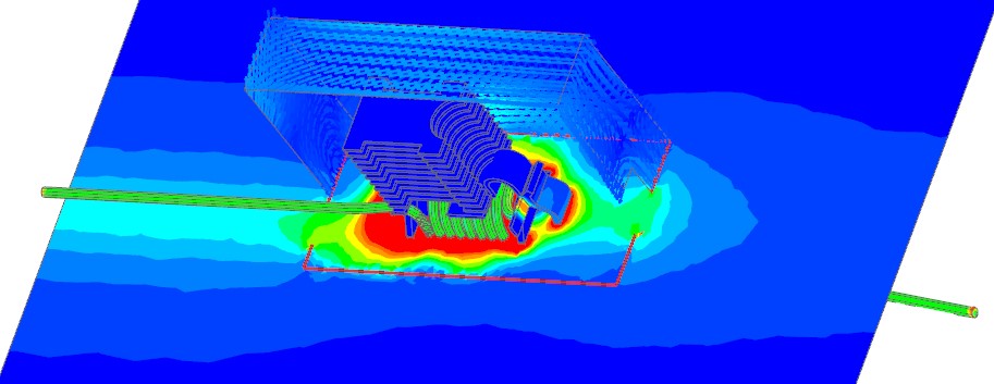 Picture: A section through the Air volume shows the Magnetic Flux Density. The shielding effect of the Carbon Box is visible
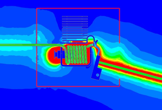 Picture: Another section through the Air volume shows the Magnetic Flux Density


