

In this application case we perform a FEM analysis with parameter identification and circuit simulation of a universal motor. The typical characteristics speed and current over torque are determined.
Initial Situation
Determine Typical Characteristics
In this application we demonstrate how to determine the typical characteristics of a universal or series-wound motor. Operating in a range less than 1000 watts these motors are widely used in many domestic appliancations such as drilling machines, vacuum cleaners and food mixers.
")
Picture: Universalmotor from a vacuum cleaner (Wikipedia)
The machine is called a series motor because the excitation winding is connected in series with the rotor winding. Further on, it is called universal motor because it can be operated with both AC and DC supplies.
The speed of a universal motor can be very high, typically in the range of 5000-30000 rpm. The speed is entirely dependent on the load and the supply voltage. Without load, a universal motor may reach dangerously high speeds. In fact, the no-load speed is only limited by friction and windage losses.
Given are technical drawing from for the section as well as the winding scheme in a typical format.

Picture: CAD Model of section of the examined universalmotor
The methods shown here base on the following literature: H. Grop “Modeling of a universal motor with speed control”, Royal Institute of Technology Department of Electrical Engineering Electrical Machines and Power Electronics, Stockholm 2006.

Picture: Winding-Scheme
Appropriate Method
Equivalent Circuit and System Equations
According to the literature the following equivalent circuit with the associated system equations for the universal motor is used.

Picture: Equivalent Circuit for Universalmotor
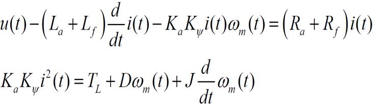
Ra, Rf: rotor and field winding resistance,
La, Lf: rotor and field winding inductance,
u(t): terminal voltage,
e(t): back emf,
i(t): current in the machine,
D: viscous damping constant,
J: moment of inertia of machine and load,
T(t), Tl: electromagnetic and load torque,
ωm(t): angular velocity of machine,
Ka: Rotor constant (known parameters),
Kψ: Flux constant.
Parameteridentification
Unknown or non-linear parameters that depend on the magnetic saturation are the inductance of the field winding Lf and the flux constant Kψ. These parameters are determined with the aid of Magnetics for NX.
Therefore a non-linear FEM model of the machine in NX is built with the magnetics solver. The nonlinear BH curves of the material electrical sheets were taken from the distributor.
We apply current varying from 0,1 to 20 Amperes to the coils in order to calculate the fields and to account for the effects of nonlinear saturation. From the results we derive the values Lf and the magnetic flux passing through a pole both as function of current as you can see in the two pictures.
 Picture: Inductivity identified as Function of Current
 Picture: Flux over Airgap identified by FEM Analysis
From the circuit and equations we now can derive a systems simulation model. This model is fed by the FEM computed values Lf(i) and Flux(i). These are included as lookup tables.
Result
Speed and Current over Torque
The systems model can be solved to find many different results. The next two images show the behaviour of speed and current over torque.
 Picture: Speed over Torque Result

Picture: Current over Torque Result
Fluxdensity and Potentiallines
Other interesting results from the FEM analysis include the fluxdensity. This plot gives useful information about utilization of geometry and material.

Picture: Fluxdensity in Contourplot

Picture: Fluxdensity as Vectorplot
Potentiallines can also give useful information. The following image shows the direction of torque and rotation: This motor will run counterclockwise.

Picture: Potentiallines show direction of torque
")
")