In this showroom example we perform a FEM analysis of a 3KW induction motor.
Download as PDF Download NX Files
The analysis is completely done in NX / Simcenter. No parameter identification and system simulation is necessary. The typical characteristics speed and current over torque are determined.
Initial Situation
Four-Pole Induction Machine Simulation
The task is to study typical characteristics such as torque and phase current behavior over the slip, as well as others. The NX CAD model is built up in a parametrically way using synchronous modeling tools and therefore it allows studying variations easily.
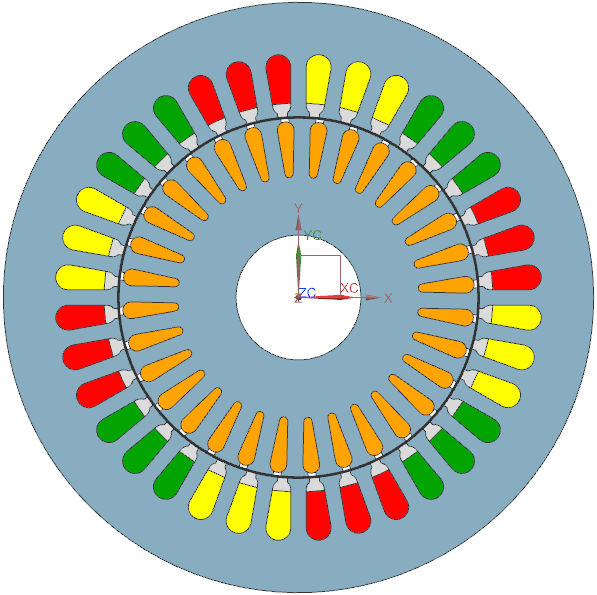 Picture: 3 KW Induction Motor
Some input data:
- Input Voltage (rms) 220 V
- Number of Poles: 4
- Number of windings per slot: 17
- Cage: Alu,
- Rotor, Stator: Electrosheet
- Velocity: 1500 U/min (sync)
Following are some references to other work regarding this motor:
- J. Gyselinck, "Twee dimensionale dynamische eindige-elementenmodellering van statische en roterende elektromagnetische energieomzetters", Ph.D. Thesis, Universiteit Gent, 2000.
- J. Gyselinck, L. Vandevelde, J. Melkebeek, "Multi-slice modeling of electrical machines with skewed slots - The skew discretization error”, IEEE Trans. Magn., 37(5):3233–3237, 2002.
- J. Gyselinck, L. Vandevelde, P. Dular, C. Geuzaine, W. Legros, "A general method for the frequency domain FE modelling of rotating electromagnetic devices", IEEE Trans. Magn., 39(3):1147-1150, 2003
Appropriate Method
Magnetodynamic Analysis in Frequency Domain
In the CAD model all slot and bar faces have names assigned to them. These names allow the automatized building of the FEM model in NX using the AUTOFEM function that belongs to the Magnetics solver kit. This tool works in the following steps:
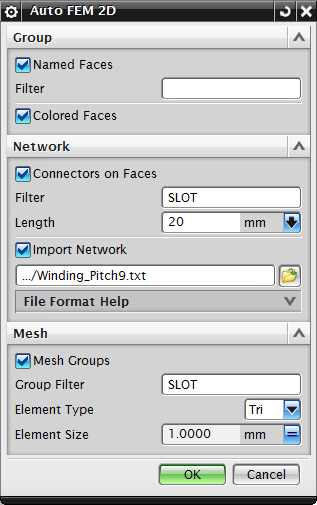 Picture: AUTO FEM Tool for automatic Generation of Analysis Models
After the meshes and circuits are built all physical properties are assigned to them. Therefore we assign properties (library-material, number of turns, ...) to one slot and copy these property to all others. In the NX simulation file we assign a motion condition and the currents for U, V, W. All these parameters are stored as NX expressions and allow easily modification.
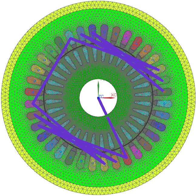 Picture: Automatically generated FEM Model: Meshes and Circuits for the Windings
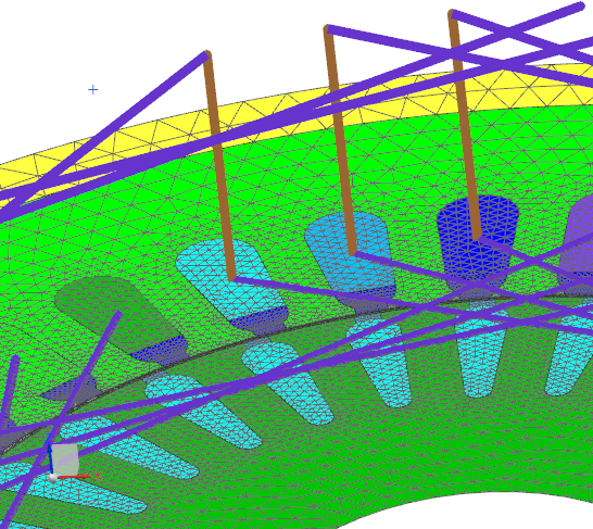 Picture: Detailed View to some Windings and Slots
Result
Frequency Sweep over Rotor Slip
The analysis is done using a parameter sweep function that sweeps the slip velocity of the rotor over the desired range. Results are the torque and phase currents.
 Picture: Torque over Speed Result
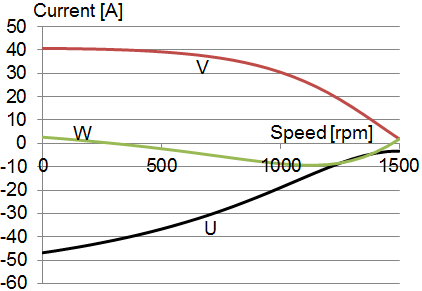 Picture: Current over Torque Result
Fluxdensity and Potentiallines
Other interesting results from the FEM analysis include the fluxdensity. This plot gives useful information about utilization of geometry and material.
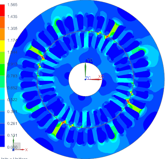 Picture: Fluxdensity in Contourplot
Potentiallines can also give useful information. The following image shows the direction of torque and rotation: This motor will run counterclockwise.
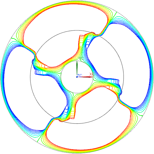 Picture: Potentiallines show direction of torque


