In this example two current carrying conductors and a permanent magnet are examined for the force acting on them. The nodal forces (Lorenz forces) are calculated in Magnetics for NX/Simcenter. Then the forces are transferred into a structural analysis where we calculate for deformations.
Initial Situation
Deforming Conductors
In this example two current carrying conductors and a permanent magnet have to be examined for the force acting on them. Those forces shall then be used to find the deformations of the two conductors.
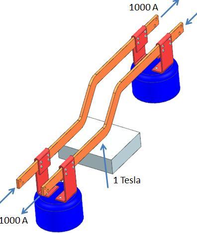
The picture shows the CAD model of the two conductors. The white block on the bottom is a permanent magnet. The currents are 1000 A, static and point in opposite directions.
 Picture: Description of the Boundary Conditions
In this case we analyze a static situation. In another analysis the task will be to compute for eddy currents and temperature effects resulting from alternating current.
Appropriate Method
Magnetics and Nastran Coupling
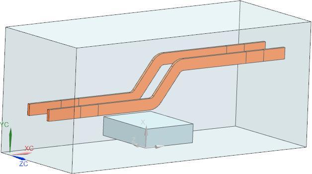
To analyze for this problem the geometry is prepared and simplified in NX Advanced Simulation. The FEM model only contains the two conductors and the magnet. Additionally a block of air was created around the geometry.
 Picture: The prepared CAD Geometry
For the mesh of the conductors we use hexahedral elements. These are of good use when having those types of geometry.
 Picture: Hexahedral Elements for the Conductors
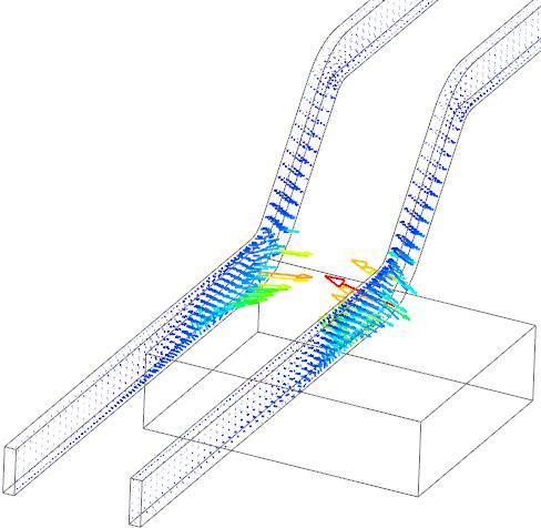
We apply boundary conditions and set up a magnetostatic solution. The solve computes nodal forces on the conductors. These forces are stored in a table file. The next picture shows these nodal forces.
 Picture: Nodal Forces Calculated by the Magnetostatic Analysis
In the next step the calculated nodal forces are stored in a spatial field definition. Also a new model for the following structural analysis is set up. Maybe in the structural analysis there have to be different conditions and parts included. In our case we simply use the same mesh for the conductors; we only deactivate the air and the magnet.
Result
Deformations and Stresses
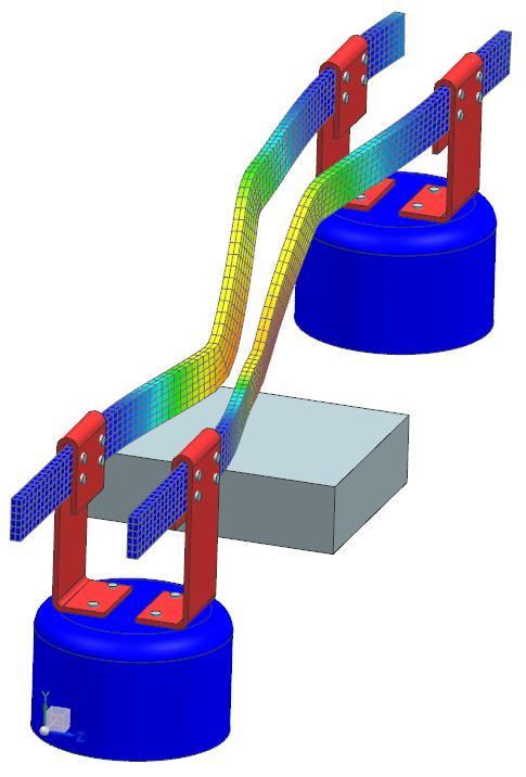
We apply appropriate boundary conditions to the structural model. The magnetic forces are applied using NX's powerful spacial field function that allows interpolating the nodal forces from magnetics even on a different mesh in the structural solution. After the solve there are all usual results from the NX/Nastran solution available. The picture shows a plot of the computed deformations.
 Picture: The calculated Deformations. (Click to animate)
This analysis gives you the possibility to calculate the deformations that result from magnetic forces. Because of the powerful integration of Magnetics and NX' structural solvers you can also take advantage of all other possibilities inside NX/Nastran.


